Difference between revisions of "Comparator"
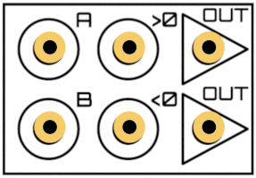
(Created page with "thumb|The six different jacks of a single Comparator The '''Comparator''' is a analog-digital logic element which puts different signals on the output...") |
(better formulation, because it doesn't matter which signal is inverted) |
||
| (5 intermediate revisions by 3 users not shown) | |||
| Line 1: | Line 1: | ||
[[File:Comparator.png|thumb|The six different jacks of a single Comparator]] | [[File:Comparator.png|thumb|The six different jacks of a single Comparator]] | ||
| − | The '''Comparator''' is a | + | The '''Comparator''' is a logic element which puts different signals on the output, depending on the input. [[The Analog Thing]] features two comparators. |
| − | Given two inputs <code>A</code> and <code>B</code>, the comparator tests | + | Given two inputs <code>A</code> and <code>B</code>, the comparator tests whether the sum of the two input values is larger or smaller zero. If it is larger, the input <code>>0</code> is directed to <code>OUT</code>, if smaller, the input <code><0</code> is directed to <code>OUT</code>. |
| − | Technically, the | + | If you want to compare two signals, one of them must be inverted before you connect them to inputs <code>A</code> and <code>B</code>. |
| + | |||
| + | Technically, the comparators of THAT are implemented with Schmitt Triggers and two analog switches. See [[:File:Anathing_v1.0_base_4.pdf]] for the schematics. | ||
| + | |||
| + | The schematic is not incomplete - the input resistor networks are located on the front panel (as for the summers, inverters, and integrators). | ||
[[Category:Components of The Analog Thing]] | [[Category:Components of The Analog Thing]] | ||
Latest revision as of 09:10, 27 September 2021
The Comparator is a logic element which puts different signals on the output, depending on the input. The Analog Thing features two comparators.
Given two inputs A and B, the comparator tests whether the sum of the two input values is larger or smaller zero. If it is larger, the input >0 is directed to OUT, if smaller, the input <0 is directed to OUT.
If you want to compare two signals, one of them must be inverted before you connect them to inputs A and B.
Technically, the comparators of THAT are implemented with Schmitt Triggers and two analog switches. See File:Anathing_v1.0_base_4.pdf for the schematics.
The schematic is not incomplete - the input resistor networks are located on the front panel (as for the summers, inverters, and integrators).
