Difference between revisions of "Panel Meter"
From TheAnalogThing
Jwdietrich (talk | contribs) m (→Monitoring Values: clarification) |
|||
| (8 intermediate revisions by one other user not shown) | |||
| Line 1: | Line 1: | ||
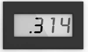
[[File:Voltmeter.png|thumb|Illustration of the display, showing the value <code>0.314</code>]] | [[File:Voltmeter.png|thumb|Illustration of the display, showing the value <code>0.314</code>]] | ||
| − | + | The '''panel meter''' is the LCD display unit located in the lower right on the upper PCB. | |
== Usage == | == Usage == | ||
| − | + | Depending on the position of the <code>MODE SELECTOR</code> knob, the '''panel meter''' is used to monitor either values or OP-TIMEs (operation times): | |
| − | + | === Monitoring Values === | |
| − | + | With the <code>MODE SELECTOR</code> knob in the <code>COEFF</code>, <code>MINION</code>, <code>IC</code>, <code>OP</code> or <code>HALT</code> positions, the panel meter displays values numerically in the unit range -1 to 1. | |
| − | + | * With the <code>MODE SELECTOR</code> knob in the <code>COEFF</code> position, the panel meter displays the output value of the <code>COEFF</code> potentiometer selected using the <code>COEFFICIENT SELECTOR</code>. This allows setting the values of coefficient potentiometers exactly to their desired values. | |
| + | * With the <code>MODE SELECTOR</code> knob in the <code>MINION</code>, <code>IC</code>, <code>OP</code> or <code>HALT</code> positions, the panel meter displays the value patched into the <code>U</code> socket in the <code>OUTPUT JACKS</code> section. This allows monitoring the values of arbitrary positions on the patch panel. | ||
| − | + | === Monitoring OP-TIMEs === | |
| − | + | With the <code>MODE SELECTOR</code> knob in the <code>REP</code> or <code>REPF</code> positions, the panel meter displays the current <code>OP TIME</code>, which can be changed by turning the <code>OP-TIME POTENTIOMETER</code>. | |
| − | + | ||
| + | * With the <code>MODE SELECTOR</code> knob in the <code>REP</code> position (i.e., in repeat mode), the <code>OP TIME</code> is shown in the 0 to 10 second range. | ||
| + | * With the <code>MODE SELECTOR</code> knob in the <code>REPF</code> position (i.e., in repeat fast mode), the <code>OP TIME</code> is shown in the 0 to 100 millisecond range. | ||
[[Category:Components of The Analog Thing]] | [[Category:Components of The Analog Thing]] | ||
Latest revision as of 10:00, 9 January 2025
The panel meter is the LCD display unit located in the lower right on the upper PCB.
Usage
Depending on the position of the MODE SELECTOR knob, the panel meter is used to monitor either values or OP-TIMEs (operation times):
Monitoring Values
With the MODE SELECTOR knob in the COEFF, MINION, IC, OP or HALT positions, the panel meter displays values numerically in the unit range -1 to 1.
- With the
MODE SELECTORknob in theCOEFFposition, the panel meter displays the output value of theCOEFFpotentiometer selected using theCOEFFICIENT SELECTOR. This allows setting the values of coefficient potentiometers exactly to their desired values. - With the
MODE SELECTORknob in theMINION,IC,OPorHALTpositions, the panel meter displays the value patched into theUsocket in theOUTPUT JACKSsection. This allows monitoring the values of arbitrary positions on the patch panel.
Monitoring OP-TIMEs
With the MODE SELECTOR knob in the REP or REPF positions, the panel meter displays the current OP TIME, which can be changed by turning the OP-TIME POTENTIOMETER.
- With the
MODE SELECTORknob in theREPposition (i.e., in repeat mode), theOP TIMEis shown in the 0 to 10 second range. - With the
MODE SELECTORknob in theREPFposition (i.e., in repeat fast mode), theOP TIMEis shown in the 0 to 100 millisecond range.
