Difference between revisions of "Hindmarsh-Rose neuron model"
m (+typo) |
|||
| (5 intermediate revisions by 2 users not shown) | |||
| Line 3: | Line 3: | ||
This is desribed as a system of three coupled differential equations: | This is desribed as a system of three coupled differential equations: | ||
| − | [[File:hindmarsh_rose_equations.jpg| | + | [[File:hindmarsh_rose_equations.jpg|256px]] |
with the parameter a=1, b=3, c=1, d=5, r=0.001, s=4 and xr=-8/5 and initial conditions of 2 for all three equations. This system of equations and parameters must be, of course, scaled for implementation on an analog computer. The resulting program looks like this: | with the parameter a=1, b=3, c=1, d=5, r=0.001, s=4 and xr=-8/5 and initial conditions of 2 for all three equations. This system of equations and parameters must be, of course, scaled for implementation on an analog computer. The resulting program looks like this: | ||
| − | [[File: | + | [[File:Hindmarsh_rose_prg.pdf|768px]] |
| + | |||
| + | The output of the simulated neuron is x, while Iext represents the input to the neuron. Setting Iext to +1 will cause the neuron to burst with sequences of spikes as shown in this actual screen shot from a digital oscilloscope: | ||
| + | |||
| + | [[File:Hindmarsh_rose_result.jpg|768px]] | ||
| + | |||
| + | The actual implementation of this program looks like this: | ||
| + | |||
| + | [[File:Hindmarsh_rose_program.jpg|512px]] | ||
| + | |||
| + | [[Category:Applications]] | ||
Latest revision as of 14:46, 25 August 2021
Beginning in the 20th centure, the behaviour of neurons has been described by mathematical models, beginning with Louis Lapicque's "integrate and fire" model in 1907. In the 1960s Richard FitzHugh and J. Nagumo developed a more sophisticated model. In the early 1980s, Hindmarsh and Rose published an even more realistic model of a spiking and burstin neuron, the Hindmarsh-Rose model.
This is desribed as a system of three coupled differential equations:
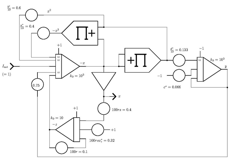
with the parameter a=1, b=3, c=1, d=5, r=0.001, s=4 and xr=-8/5 and initial conditions of 2 for all three equations. This system of equations and parameters must be, of course, scaled for implementation on an analog computer. The resulting program looks like this:
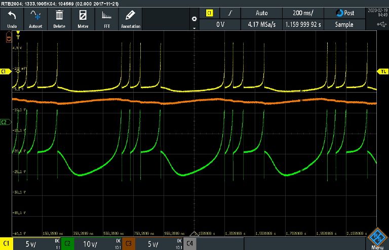
The output of the simulated neuron is x, while Iext represents the input to the neuron. Setting Iext to +1 will cause the neuron to burst with sequences of spikes as shown in this actual screen shot from a digital oscilloscope:
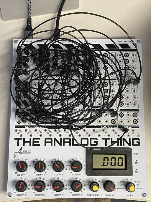
The actual implementation of this program looks like this:


