Difference between revisions of "Coefficients/Potentiometers"
From TheAnalogThing
| Line 7: | Line 7: | ||
* The <code>MODE</code> selector. | * The <code>MODE</code> selector. | ||
* The <code>COEFFICIENT</code> selector. | * The <code>COEFFICIENT</code> selector. | ||
| − | * The | + | * The <code>PANEL METER</code>. |
To familiarize yourself with the use of coefficient potentiometers, follow these steps: | To familiarize yourself with the use of coefficient potentiometers, follow these steps: | ||
| − | # Set the <code>MODE</code> selector to position <code>COEFF</code> and set the <code>COEFFICIENT</code> selector to position <code>1</code>. This connects the output of potentiometer <code>COEFF 1</code> to the | + | # Set the <code>MODE</code> selector to position <code>COEFF</code> and set the <code>COEFFICIENT</code> selector to position <code>1</code>. This connects the output of potentiometer <code>COEFF 1</code> to the <code>PANEL METER</code>. |
# Use a patch cable to connect one of the <code>+1</code> jacks in the <code> STABILIZED ±1</code> section to the input (circle) associated with potentiometer <code>COEFF 1</code> in the <code>COEFFICIENTS</code> section (i.e., the uppermost circled jack in the section labelled <code>COEFF</code> on your THAT). | # Use a patch cable to connect one of the <code>+1</code> jacks in the <code> STABILIZED ±1</code> section to the input (circle) associated with potentiometer <code>COEFF 1</code> in the <code>COEFFICIENTS</code> section (i.e., the uppermost circled jack in the section labelled <code>COEFF</code> on your THAT). | ||
| − | # Change the position of the <code>COEFF 1</code> knob in the <code>COEFFICIENT POTENTIOMETERS</code> section and observe the value displayed on the | + | # Change the position of the <code>COEFF 1</code> knob in the <code>COEFFICIENT POTENTIOMETERS</code> section and observe the value displayed on the <code>PANEL METER</code>. The displayed value is available at the output (triangle) associated with potentiometer <code>COEFF 1</code> in the <code>COEFFICIENT</code> section. |
# Remove the patch cable plug from the <code>+1</code> jack in the <code> STABILIZED ±1</code> section and plug it into one of the <code>-1</code> jacks in in the <code> STABILIZED ±1</code>. | # Remove the patch cable plug from the <code>+1</code> jack in the <code> STABILIZED ±1</code> section and plug it into one of the <code>-1</code> jacks in in the <code> STABILIZED ±1</code>. | ||
| − | # Again, change the position of the <code>COEFF 1</code> knob in the potentiometer section and observe the value displayed on the | + | # Again, change the position of the <code>COEFF 1</code> knob in the potentiometer section and observe the value displayed on the <code>PANEL METER</code>. |
# Set the <code>COEFFICIENT</code> selector to any one of the other potentiometers (say, 4). | # Set the <code>COEFFICIENT</code> selector to any one of the other potentiometers (say, 4). | ||
# Use a patch cable to connect either of the <code>-1</code> jacks in the <code> STABILIZED ±1</code> with the input (circle) associated with the with the coefficient potentiometer you have chosen using the <code>COEFFICIENT</code> selector (say, 4). | # Use a patch cable to connect either of the <code>-1</code> jacks in the <code> STABILIZED ±1</code> with the input (circle) associated with the with the coefficient potentiometer you have chosen using the <code>COEFFICIENT</code> selector (say, 4). | ||
| − | # Change the position of the coefficient potentiometer knob associated with the coefficient you have chosen using the <code>COEFFICIENT</code> selector (say, 4) and again observe the value displayed on the | + | # Change the position of the coefficient potentiometer knob associated with the coefficient you have chosen using the <code>COEFFICIENT</code> selector (say, 4) and again observe the value displayed on the <code>PANEL METER</code>. |
[[File:THAT_legend_potentiometers_s.png|thumb|left|800px|Figure 1: Parts of the THAT user interface that relate to the familiarization steps described above]] | [[File:THAT_legend_potentiometers_s.png|thumb|left|800px|Figure 1: Parts of the THAT user interface that relate to the familiarization steps described above]] | ||
[[Category:Components of The Analog Thing]] | [[Category:Components of The Analog Thing]] | ||
Revision as of 15:20, 8 August 2021
Coefficients are quantitative parameters that enter analog computations in a multiplicative fashion. The Analog Thing features eight coefficient potentiometers, allowing the use of up to eight coefficients in an analog computation. Using the potentiometers, each coefficient can be set to any value between 0 and +1. An input to a coefficient potentiometer is multiplied by the value the coefficient potentiometer is set to such that their output is given by output = coefficient * input.
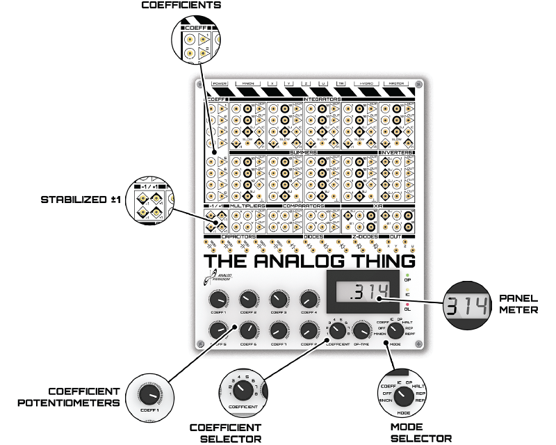
Several sections of the THAT user interface relate to the use of coefficient potentiometers, as shown in Figure 1:
- The
COEFFICIENTSsection. This is the area labelledCOEFFon your THAT. It contains the inputs and output sockets for the coefficient potentiometers. - The
COEFFICIENT POTENTIOMETERSsection. - The
MODEselector. - The
COEFFICIENTselector. - The
PANEL METER.
To familiarize yourself with the use of coefficient potentiometers, follow these steps:
- Set the
MODEselector to positionCOEFFand set theCOEFFICIENTselector to position1. This connects the output of potentiometerCOEFF 1to thePANEL METER. - Use a patch cable to connect one of the
+1jacks in theSTABILIZED ±1section to the input (circle) associated with potentiometerCOEFF 1in theCOEFFICIENTSsection (i.e., the uppermost circled jack in the section labelledCOEFFon your THAT). - Change the position of the
COEFF 1knob in theCOEFFICIENT POTENTIOMETERSsection and observe the value displayed on thePANEL METER. The displayed value is available at the output (triangle) associated with potentiometerCOEFF 1in theCOEFFICIENTsection. - Remove the patch cable plug from the
+1jack in theSTABILIZED ±1section and plug it into one of the-1jacks in in theSTABILIZED ±1. - Again, change the position of the
COEFF 1knob in the potentiometer section and observe the value displayed on thePANEL METER. - Set the
COEFFICIENTselector to any one of the other potentiometers (say, 4). - Use a patch cable to connect either of the
-1jacks in theSTABILIZED ±1with the input (circle) associated with the with the coefficient potentiometer you have chosen using theCOEFFICIENTselector (say, 4). - Change the position of the coefficient potentiometer knob associated with the coefficient you have chosen using the
COEFFICIENTselector (say, 4) and again observe the value displayed on thePANEL METER.
