Difference between revisions of "Integrator"
| (16 intermediate revisions by 4 users not shown) | |||
| Line 1: | Line 1: | ||
| − | '''Integrators''' are the essential building blocks of analog computers. They perform '''integration in time''', as in <code> | + | '''Integrators''' are the essential building blocks of analog computers. They perform '''integration in time''', as in <code>F(t) = F(0) - ʃ_0^t f(t')/k0 dt'</code>. [[The Analog Thing]] features five integrators. This allows computing five integrals in a program. |
Electronic analog computers typically perform integration by charging and discharging capacitors. The key difference between an integrator and a [[summer]] is the capacity in the feedback channel instead of a simple resistance. Accordingly, all integrators are also summing their inputs. For more details, please refer to [[Literature|Analog computing literature]]. | Electronic analog computers typically perform integration by charging and discharging capacitors. The key difference between an integrator and a [[summer]] is the capacity in the feedback channel instead of a simple resistance. Accordingly, all integrators are also summing their inputs. For more details, please refer to [[Literature|Analog computing literature]]. | ||
| Line 9: | Line 9: | ||
* Analog integrators sum their inputs. That is, if you have a sum under your integral, you can save a single summer before the integrator. Otherwise, just put your integrand into the upper left input labeled with <code>1</code>. | * Analog integrators sum their inputs. That is, if you have a sum under your integral, you can save a single summer before the integrator. Otherwise, just put your integrand into the upper left input labeled with <code>1</code>. | ||
* There are two output slots. Just use one of them as you like. | * There are two output slots. Just use one of them as you like. | ||
| − | * The <code>IC</code> slot stands for ''initial conditions''. It is an input where you have to provide suitable initial conditions. As shorthands, <code>-1</code> and <code>+1</code> are right to the hand. If this slot is left empty, <code>0</code> is taken as initial condition. | + | * The <code>IC</code> slot stands for ''initial conditions''. It is an input where you have to provide suitable initial conditions, i.e. specify what value <code>F(0)</code> should take. As shorthands, <code>-1</code> and <code>+1</code> are right to the hand. If this slot is left empty, <code>0</code> is taken as initial condition. |
* Beginners may ignore the slots <code>SJ</code> and <code>SLOW</code>. | * Beginners may ignore the slots <code>SJ</code> and <code>SLOW</code>. | ||
| − | + | * The integrator's constant k0 is defined as k0 = 1/(R*C), which means the unit of k0 is [1/s] (Source: "Analogrechnen" by Giloi and Lauber, on the page before page 1). For THAT's integrators the constant is k0 = 1000 s^-1 in normal mode, or k0 = 10 s^-1 in <code>SLOW</code> mode. | |
| − | [ | + | * The integration time scale factor of the <code>1</code> inputs is 1ms (1MOhm * 1nF = 1ms). That means if you connect a <code>-1</code> signal to a <code>1</code> input, the output will ramp from 0 to 1 machine unit in 1ms. The <code>10</code> inputs have a integration time scale factor of 100μs (100kOhm * 1nF = 100μs), meaning in the aforementioned scenario the signal rises ten times faster from 0 to 1 when using a <code>10</code> input instead of a <code>1</code> input. In <code>SLOW</code> mode the integration time scale factors are 100ms for <code>1</code> inputs or 10ms for <code>10</code> inputs. |
== Extended Usage of an Integrator == | == Extended Usage of an Integrator == | ||
| + | === Changing the integration speed === | ||
| + | [[File:Slow-integrator.png|thumb|Internal wiring and effect of slowing down integrator. Source: [[:File:Anathing v1.0 base 3.pdf]].]] | ||
| − | + | You can change the integration time scale factors <code>k0</code> of a particular integrator by connecting <code>SLOW</code> to <code>OUT</code>. This increases the time scale factors of the respective integrator by a factor of approximately 100. For the constant integration scenario described above, this means the output takes 100 times longer to transition from 0 to 1 than for the same inputs with <code>SLOW</code> disconnected. | |
| − | + | You can also increase the time scale factor by 10, if you connect an external 10nF capacitor between <code>SLOW</code> and <code>OUT</code>. | |
| − | |||
| − | |||
| − | You can | ||
=== Making use of the Summing junction === | === Making use of the Summing junction === | ||
| + | To extend the number of inputs, connect the SJ panel of the integrator to the SJ panel of a XIR element. Now the other panels of the corresponding XIR element function as inputs of the connected integrator. | ||
See also [[XIR]]. | See also [[XIR]]. | ||
| Line 29: | Line 29: | ||
On an electronical level, Integrators work quite similar to [[Summer]]s (and [[Inverter]]s, respectively), given the closed-loop operational amplifier setup. However, they feature a capacitor in the feedback channel which holds the current integration level. This makes an integrator ''stateful'' in contrast to the ''stateless'' Summers. | On an electronical level, Integrators work quite similar to [[Summer]]s (and [[Inverter]]s, respectively), given the closed-loop operational amplifier setup. However, they feature a capacitor in the feedback channel which holds the current integration level. This makes an integrator ''stateful'' in contrast to the ''stateless'' Summers. | ||
| − | In the [[THAT]] circuits, you find the integrators on page [[:File:Anathing_v1.0_base_3.pdf]]. As you can see there, they are implemented with ICs called <code> | + | In the [[THAT]] circuits, you find the integrators on page [[:File:Anathing_v1.0_base_3.pdf]]. As you can see there, they are implemented with ICs called <code>TL074H</code>. See [https://www.ti.com/lit/ds/symlink/tl074h.pdf?ts=1628761245896&ref_url=https%253A%252F%252Fwww.ti.com%252Fproduct%252FTL074H] for the datasheet of this chip. |
{{todo|write more}} | {{todo|write more}} | ||
| − | |||
[[Category:Components of The Analog Thing]] | [[Category:Components of The Analog Thing]] | ||
Latest revision as of 08:59, 12 June 2024
Integrators are the essential building blocks of analog computers. They perform integration in time, as in F(t) = F(0) - ʃ_0^t f(t')/k0 dt'. The Analog Thing features five integrators. This allows computing five integrals in a program.
Electronic analog computers typically perform integration by charging and discharging capacitors. The key difference between an integrator and a summer is the capacity in the feedback channel instead of a simple resistance. Accordingly, all integrators are also summing their inputs. For more details, please refer to Analog computing literature.
Basic Usage of an Integrator on The Analog Thing
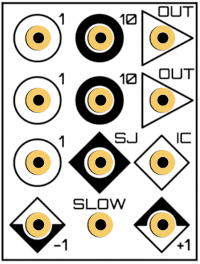
- Circles represent inputs, triangles represent outputs
- Analog integrators sum their inputs. That is, if you have a sum under your integral, you can save a single summer before the integrator. Otherwise, just put your integrand into the upper left input labeled with
1. - There are two output slots. Just use one of them as you like.
- The
ICslot stands for initial conditions. It is an input where you have to provide suitable initial conditions, i.e. specify what valueF(0)should take. As shorthands,-1and+1are right to the hand. If this slot is left empty,0is taken as initial condition. - Beginners may ignore the slots
SJandSLOW. - The integrator's constant k0 is defined as k0 = 1/(R*C), which means the unit of k0 is [1/s] (Source: "Analogrechnen" by Giloi and Lauber, on the page before page 1). For THAT's integrators the constant is k0 = 1000 s^-1 in normal mode, or k0 = 10 s^-1 in
SLOWmode. - The integration time scale factor of the
1inputs is 1ms (1MOhm * 1nF = 1ms). That means if you connect a-1signal to a1input, the output will ramp from 0 to 1 machine unit in 1ms. The10inputs have a integration time scale factor of 100μs (100kOhm * 1nF = 100μs), meaning in the aforementioned scenario the signal rises ten times faster from 0 to 1 when using a10input instead of a1input. InSLOWmode the integration time scale factors are 100ms for1inputs or 10ms for10inputs.
Extended Usage of an Integrator
Changing the integration speed

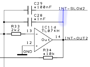
You can change the integration time scale factors k0 of a particular integrator by connecting SLOW to OUT. This increases the time scale factors of the respective integrator by a factor of approximately 100. For the constant integration scenario described above, this means the output takes 100 times longer to transition from 0 to 1 than for the same inputs with SLOW disconnected.
You can also increase the time scale factor by 10, if you connect an external 10nF capacitor between SLOW and OUT.
Making use of the Summing junction
To extend the number of inputs, connect the SJ panel of the integrator to the SJ panel of a XIR element. Now the other panels of the corresponding XIR element function as inputs of the connected integrator. See also XIR.
Mathematics and Electronics about analog integration
On an electronical level, Integrators work quite similar to Summers (and Inverters, respectively), given the closed-loop operational amplifier setup. However, they feature a capacitor in the feedback channel which holds the current integration level. This makes an integrator stateful in contrast to the stateless Summers.
In the THAT circuits, you find the integrators on page File:Anathing_v1.0_base_3.pdf. As you can see there, they are implemented with ICs called TL074H. See [1] for the datasheet of this chip.
