Soundcard Oscilloscope
You can use the Soundcard of your computer or mobile device as an analog input/output interface to The Analog Thing. This page explains about details and gives recommendations about suitable hardware and software. Using the soundcard has the advantage of being very cheap (suitable soundcards in the range of 20€) compared to a real Oscilloscope (starting at 150€). The drawback are noticable skews and deviations in the data aquisition (for details see below)
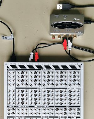
An alternative to the missing inbuild audio input is a USB device. There are not many line-in stereo devices and most are only mono to use with microphones. A well tested device was the Behringer UFO202 with line-in and line out (each stereo) which is connected to USB, don't need any drivers and suitable for Windows, Mac and Linux in the price range of approx. 20 €. If your computer has already a microphone (mono) input you may buy a second cheap mono "microphone in" USB device for approx. 10 €. Be sure, that there is also an audio input and not just an audio output.
In order to use the soundcard as a data capture device, a software oscilloscope is required for visualization.
The Analog Thing audio connectors
The Analog Thing is already prepared to work with the above listed classic audio in devices as the used frequencies in an analog computation or simulation is mostly in the range of 20 Hz ... 20 kHz. There are 4 chinch connectors named with X, Y, Z, U which can be used either as signal output or signal input as well. The voltage range of +/- 10V of the reference voltage (representing the analog values 1.0 ... -1.0) is reduced by factor 10 to +/- 1V (representing 0.1 ... -0.1). This is a safe voltage for audio input devices (line in).
To feed signals into a soundcard you need to connect for example X and Y chinch connector to the line in jack of the computer or external sound device. Additional you must choose which signal in your analog circuit should be displayed by connecting any output of a computing element (integrator, summer, multiplier or comparator) to the OUT field on the front panel with a patch cable. If you want to input a signal to your analog circuit you do the same on the patch panel but connect the used chinch connector to an audio output. Some of the software solutions can display incoming signals but also offer signal generators additionally.
Be aware, that the chinch connectors are connected with a passive resistor divider and have a output impedance of approx. 500 Ohm. This is suitable for the audio inputs as the typical input impedance is in the range of approx 5-10 kOhm. Anyway the shown values for voltages of the software oscilloscopes are more or less an approximation or maybe can be adjusted by a factor in the configuration. Even audio outputs can often drive such impedances without problems. If an input signal of +/- 1V should be transferred in the range of +/- 10V it is easy to use the 10x input of a summer or integrator and use whose output.
Beside the chinch connectors it is easily to adapt signals directly at the patch cables with oscilloscope probes or feed signals directly with a cable adapter (cut one end of a patch cable and solder it to any signal of a programmable barebone controller board like arduino or similar.

The Analog Thing has line level outputs which are suitable for using Digital computer soundcards for data aquisition (conversion to digital). This allows to use digital computers as Software oscilloscopes.
An alternative to the missing inbuild audio input is a USB device. There are not many line-in stereo devices and most are only mono to use with microphones. A well tested device was the Behringer UFO202 with line-in and line out (each stereo) which is connected to USB, don't need any drivers and suitable for WIN, Mac and Linux in the price range of approx. 20 €. If your computer has already a microphone (mono) input you may buy a second cheap mono "microphone in" USB device for approx. 10 €. Be sure, that there is also an audio input and not just an audio output.
The Analog Thing audio connectors
The Analog Thing is already prepared to work with the above listed classic audio in devices as the used frequencies in an analog computation or simulation is mostly in the range of 20 Hz ... 20 kHz. There are 4 chinch connectors named with X, Y, Z, U which can be used either as signal output or signal input as well. The voltage range of +/- 10V of the reference voltage (representing the analog values 1.0 ... -1.0) is reduced by factor 10 to +/- 1V (representing 0.1 ... -0.1). This is a safe voltage for audio input devices (line in).
To feed signals into a soundcard you need to connect for example X and Y chinch connector to the line in jack of the computer or external sound device. Additional you must choose which signal in your analog circuit should be displayed by connecting any output of a computing element (integrator, summer, multiplier or comparator) to the OUT field on the front panel with a patch cable. If you want to input a signal to your analog circuit you do the same on the patch panel but connect the used chinch connector to an audio output. Some of the software solutions can display incoming signals but also offer signal generators additionally.
Be aware, that the chinch connectors are connected with a passive resistor divider and have a output impedance of approx. 500 Ohm. This is suitable for the audio inputs as the typical input impedance is in the range of approx 5-10 kOhm. Anyway the shown values for voltages of the software oscilloscopes are more or less an approximation or maybe can be adjusted by a factor in the configuration. Even audio outputs can often drive such impedances without problems. If an input signal of +/- 1V should be transferred in the range of +/- 10V it is easy to use the 10x input of a summer or integrator and use whose output.
Beside the chinch connectors it is easily to adapt signals directly at the patch cables with oscilloscope probes or feed signals directly with a cable adapter (cut one end of a patch cable and solder it to any signal of a programmable barebone controller board like arduino or similar.
Limitations
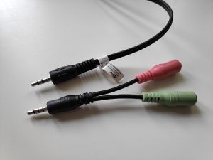
- Many soundcards only provide combi jack connectors. They typically have stereo output but mono microphone level input. Therefore, they are only suitable for single channel data aquisition. You should try to get a soundcard which has line level input, which is typically stereo and also line but not microphone level.
- Soundcards are known to have a highpass filter, so they filter out DC components. This means they are not suited for measuring static signals. They also do many kind of signal processing, and different devices will differ. Their usability for analog computing highly depends, and in the following a number of soundcards shall be enlisted:
List of known or tested soundcards
None yet, but here is a list of candidate soundcards:
- 8€ cheap mono device – Sabrent USB External Stereo Sound – https://www.amazon.de/Sabrent-Soundkarte-External-erforderlich-AU-MMSA/dp/B00IRVQ0F8/
- Fun Generation UA-202, around 20€ https://www.thomann.de/de/fun_generation_ua_202.htm
- LogiLink Soundkarte UA009, around 20€ https://www.bueromarkt-ag.de/soundkarte_logilink_ua0099_usb_sound_box_7.1,p-ua0099,l-google-css,pd-b2c.html?
- Behringer U-Control UFO202 USB Audio, around 25€ https://www.amazon.de/-/en/Behringer-U-Control-UFO202-Interface-Digitisation/dp/B096RTMS3T/ref=sr_1_4?dchild=1&keywords=USB%2Bstereo%2Binput&qid=1626208266&s=computers&sr=1-4&th=1


